
At last my plans for a skirmish board set during the Second Punic War can advance a bit more. Naturally I am very happy to share this progress with you. Last time we looked at the basics: theming and design of the board, possible materials to construct it, historical considerations (including roman viticulture and villae rusticae) and miniatures to use with the board.
This installment is all about the laser-cut frames for the modules. The design for these has been improved and the material changed from HIPS to Bamboo.
Materials for the frame – Why Bamboo?
After I raved about HIPS in the last installment it might come as a surprise that I now changed to Bamboo. The reason for this is simple: The laser service I use first told me that HIPS can be cut, however, tests with the material did result in melted edges and unsavory chlorine gas (that seems to corrode the innards of the laser). So while it is surely possible to cut HIPS with a special setup it seems not feasible in my specific location.
There were a number of alternatives: Plywood, MDF, laserable plastic, cardboard etc. Laserable plastic or acrylic is unfortunately very expensive (no comparison to the cheap HIPS).
Cardboard is not sturdy enough at the thickness I was looking at. Furthermore the edges can get dented and it might absorb water easily. That said, it is cheap and well suited for a prototype.
Plywood and MDF are the traditional materials for laser cutting. Plywood is more expensive than MDF, but it has a visible grain and depending what kind of veneer you choose all kinds of wood finishes can be achieved: Oak, birch, pine, bamboo etc. MDF is very cheap and smooth, but can be heavy. 2mm MDF is hard to source with 3 mm being the industry standard.
In the end I decided to give Bamboo veneer a go. Bamboo has a number of advantages when compared to other materials. Most important for me was weight. Bamboo has a similar density as MDF, however, it is more elastic and the strength-to-weight ratio is higher. This implies that one can use thinner sheets while not compromising on protection for the XPS core.
Through some tests I was able to confirm that a 0.9mm thick Bamboo sheet should provide enough protection and is sturdy enough for a frame. That said it needs to be supported by XPS. The frame with a filling of three sheets of XPS foam comes in at about 150g. Depending how heavy the terrain features will be I could see that a 900 mm by 900 mm board would only weight 2.5kg or less, which is really not too bad. I might also test 1.8mm Bamboo veneer to see if this can support itself.
Bamboo is also a sustainable material, which is a nice added benefit. Check if your supplier is FSC certified and make also sure that the Bamboo veneer is made using adhesives with no added urea formaldehyde. Finally the Bamboo veneer can be stained using common oil or water based wood stain. If you are after a uniform dark frame this can be achieved, but at the same time a light maroon or any other color is no problem either.
A 0.9 mm 1220 x 1220 mm sheet of Bamboo veneer costs 42.50 NZD (and I understand 1.8 mm is not much more expensive). We could thus cut about 12 modules (300 mm x 300 mm x 20 mm) out of one sheet with a variety of profiles. Accordingly the price per module frame comes to approximately 3.50 NZD. This is only 1.50 NZD more expensive than the HIPS.
Naturally we have to take the price for the laser cut into consideration. For two bases and about 10 profiles I got a quote of 15 NZD. So the price for one frame is about 7.50 NZD. We also need to add 2.88 Dollars NZ per module for the extruded polystyrene foam. Accordingly we look at 10.38 NZD. This is slightly cheaper than you can get a Back 2 Base-ix frame for. The profiles of this product do not feature inclines and are entirely flat. The frames are also significantly heavier as they use 3 mm MDF, yet they can easily stand free.
That said, if we would use MDF the cost comparison would be even better. I intend to get some more profiles cut in 3 mm MDF (or 2 mm if I can source it) and 2.5 mm pine and then compare the different materials to find the best compromise between weight and sturdiness.
Designing the profiles
After you decided on the material it is now time to design the profiles for maximum utility. No matter if you plan to get your sheets laser cut or would like to cut them by hand, accuracy is of the utmost importance. It is thus a good idea to use a vector drawing program to design your profiles. I use Adobe Illustrator, but open source software such as Inkscape is also an excellent choice.
What do we need to keep in mind when designing the profiles?
- You need to account for the kerf of the laser cutter. This can vary from machine to machine, but should not be more than 0.1 to 0.2 mm. Accordingly, if we want the modules to be exactly 300 mm we need to add 0.2 to 0.4 to account for the kerf. If you live in the states (or use imperial measurements) it is worth considering making the modules 304.8 mm, which is exactly one foot. With kerf thus 305 mm.
- You need to account for material thickness. In my case it is 0.9 mm (given there can be a 10 percent variety in material thickness I assumed 1mm to have some wiggle room), but if you for instance use 3 mm MDF you would need to change measurements accordingly. This affects the sides, and the pegs on the base. Basically one set of profiles needs to be 298.4 mm, the other set 300.4 mm, and the pegs need to be 1mm long accounting for material thickness and kerf.
- The profiles need to be symmetrical. If they are not you will not be able to combine them freely. Here the vector drawing program can shine. You have full control over measurements and can mirror, rotate and transform shapes easily. That said, if you design a river profile it looks more realistic if you place the river bed closer to one side. This limits combinations, but looks much better than straight, symmetrical river beds.
- You need some form of peg system to make sure the sides can be easily attached to the base without moving around and introducing inaccuracies.
- You might want to add some circular recesses to add magnets to the profiles. This way you can make sure that the modules won’t move when you bump against the table. You can add such recesses to the base sheet, too, and put magnetic receptive sheeting underneath. If you plan to have variations in height between modules these magnets can also be used to attach a module to a similar sized flat top module underneath to bring it to the required height.
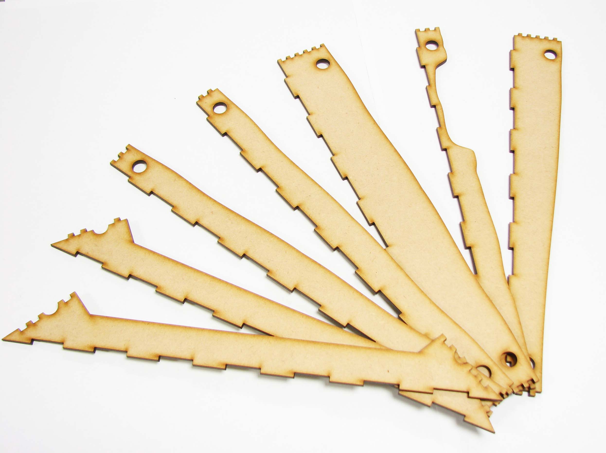
Keeping all this in mind I came up with the following set of profiles and base:
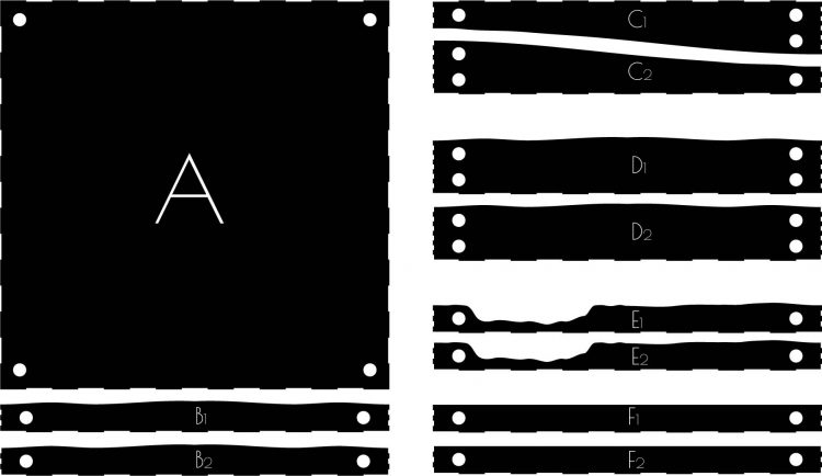
We have the base (A) and one ‘standard’ profile (B) where B1 is the female and B2 is the male part. It features a lightly undulated top. As opposed to having an entirely flat top this should help to hide transitions between modules, as the eye might be less prone to see slightly irregular lines, than straight ones.
Profile C features a gentle incline that brings the height of the module up to 4 cm. The incline does not exceed 15 degree and should thus pose no problem with miniature placement.
Profile D has the same top finish as profile B, but is 4 cm high, accordingly it fits perfectly to profile C.
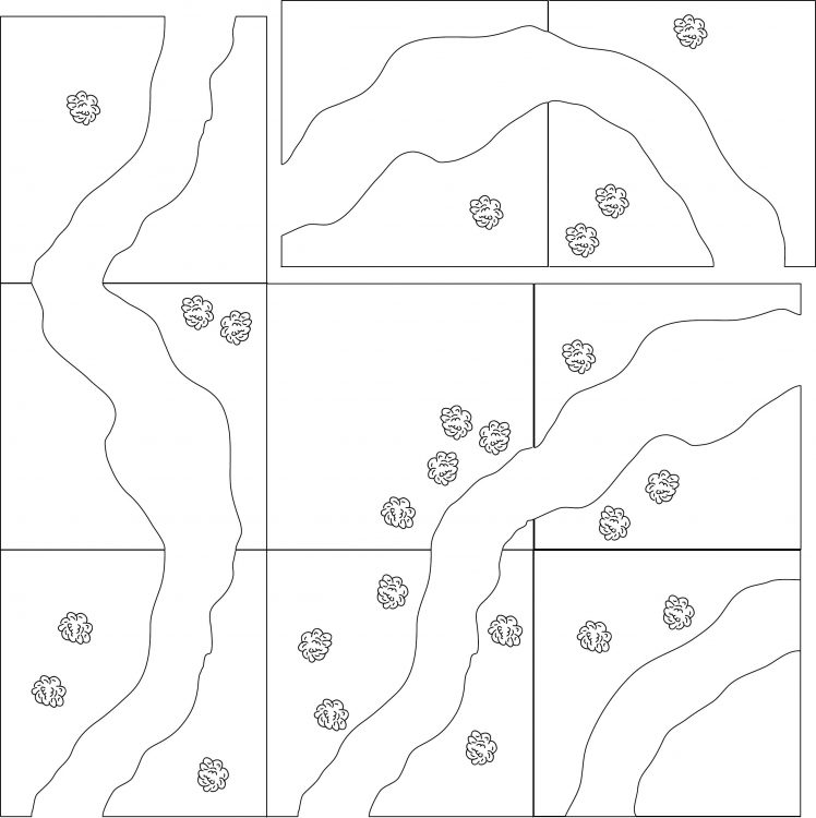
Profile E is for modules featuring a river and is unsymmetrical for added realism. That said the river profiles can still be combined with each other in a variety of ways, illustrated in the sketch below:
Finally we have Profile F, which has a flat top and can be used with Profile A if a flat profile to one side is needed (for instance to connect to a module of a friend that does comes with a flat top) or to bring Profile A to the same height as Profile C.
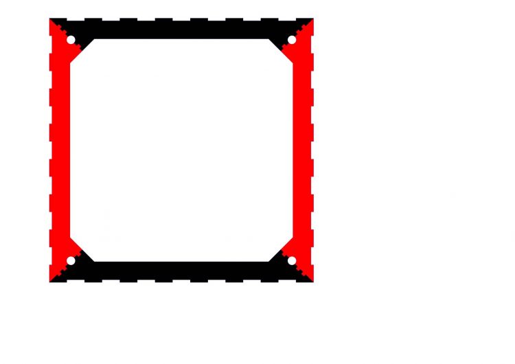
Designing the base plate
My main concern with the base plate was cost and weight. Using thin plywood seemed like a bad idea. If anyone would apply some pressure on the XPS the entire module could break. Plywood is also more expensive than MDF and noboy will see any nice wood grain.
Keeping this in mind I designed a base plate with only a thin border to support the XPS. This would reduce the weight of the module significantly, especially if using 3mm MDF. A piece of card or colored plastic could then be used to back the XPS and add more stability. I could see that a weight reduction of 40 to 50% is feasible without affecting the integrity of the base.
Prototyping
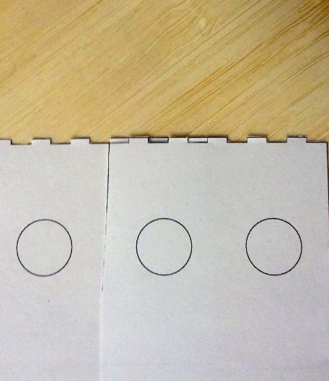
It is very important to do some prototyping before you send your design to a laser cutting service. I recommend to print out your design on some paper or card and cut it out with scissors. Obvious mistakes, inaccuracies and non matching parts will be easy to spot at this stage and apart from a need to revise your design no harm is done. Testing the female and male connectors is especially important to assure a good fit.
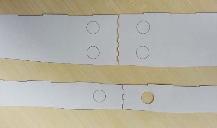
When you think you are ready it stands to reason to make a test cut in a less costly material, for instance cardboard of a similar thickness to your material of choice. Given MDF is so cheap you can easily use it for prototyping and then move to your plywood or acrylic of the same thickness. You can then check if your allowance for kerf was enough and if your pegs work out. You can also assemble this prototype and see if everything fits nicely.
The base plate worked out, too. It is sturdy enough to support the XPS, but benefits from additional backing for the XPS.

What holds the future?
Finally you can go and cut in the actual material of your choice. Again I would recommend to cut one set of profiles and the base. Then build the frame and make sure that everything works out as intended. Now final changes can be made (if necessary) and mass production can commence.
Now that we have the frames for our modular skirmish board we can start assembly. Glue in the magnets, fill the frames with XPS and heat up the hot knife (or sharpen the cutter) to carve the terrain. This will be the focus of the next installment of this series. For now a sneak preview of how I want to layout my board:
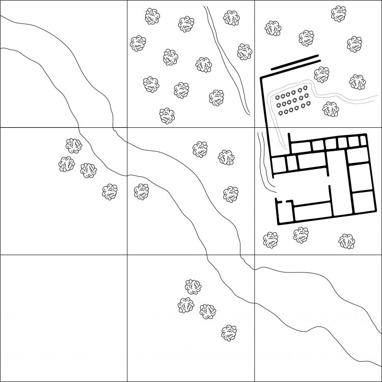
I will focus first on the four central boards, featuring the vineyard, an olive grove with part of the villa rustica (the wall of the garden), the villa rustica main building and finally a river piece. This can then be extended with five more modules that will feature further river pieces and will also have a slight incline towards the lower left edge.
I hope you found this treatise on laser-cutting gaming board frames interesting and can make use of it in your own projects. If you have suggestions how I could further improve the design or any questions comment below. In the meantime wield your brush with honor!
Thanks for going into such detail on the process! I’ve considered making my own for some time now, except I was looking to raise the “pan” in the center to use less styrofoam.
Would love to learn more about the buy-in costs for a laser cutter, and your thoughts on the one you purchased. (I’m over at hollywoodgamesco.wordpress.com.)
You are very welcome. I don’t have a laser myself, but used a reliable service which offered a large laser bed (cheaper as you can buy a large 3mm MDF sheet or acrylic sheet).
Lots of great information, especially seeing your thought process on the planning. As far as the inlays go I think either of the sword designs are the lay to go. While I like both of the other designs I really can’t see how you would align the other pieces for an inlay, unless you just intend to laser etch the finer details like the script.
Hi Brian. Thank you for your comment. Much obliged. I was thinking about the fine detail of the Iberian warrior, with soem parts being just a bit more than 1mm wide. This could pose a problem.
Online I found some instructions that might help with this: First I engrave the design into the base with the depth being 0.9mm if I would use the bamboo, then I cut the inlay out of veneer, but slightly bigger to account for the kerf. This obviously only works if the base would be thicker. I will in any case cut some of the profiles in 3mm mdf and 2.5 pine to see how that compares. Ultimately I am concerned about weight, so if I go for 3mm mdf (and can’t source 2mm) it might eb an idea to cut a geometric pattern into the base to reduce the amount of mdf to about half. This should still be fairly rigid, make the module light and also add visual interest.
Very nice idea indeed ! Keep up the good work!
Hi Thomas. Thank you for your comment. I am glad you found the tutorial useful. I might also cut some 3 mm mdf and 2.5 mm pine versions to get an idea how they compare to Bamboo.
I have to redo the tiles I have from TSS so I am grateful for all ideas concerning terrain tiles at the mo!